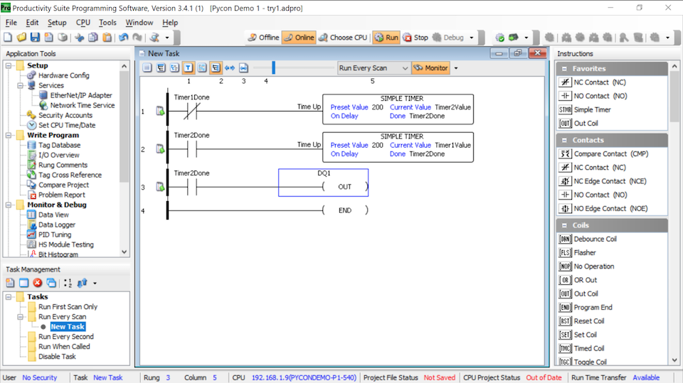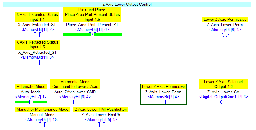
Each coil or contact corresponds to the status of a single bit in the programmable controller's memory. Ladder logic has contacts that make or break circuits to control coils. The analogy between logical propositions and relay contact status is due to Claude Shannon. If no path can be traced, then the output is false (0) and the "coil" by analogy to electromechanical relays is considered "de-energized". If a path can be traced between the left side of the rung and the output, through asserted (true or "closed") contacts, the rung is true and the output coil storage bit is asserted (1) or true. The language itself can be seen as a set of connections between logical checkers (contacts) and actuators (coils). Proper use of programmable controllers requires an understanding of the limitations of the execution order of rungs.

By executing the loop fast enough, typically many times per second, the effect of simultaneous and immediate execution is achieved.
TESTING LADDER LOGIC PROGRAM SOFTWARE
When implemented in a programmable logic controller, the rules are typically executed sequentially by software in a continuous loop, or "scan". When implemented with relays and other electromechanical devices, the various rules execute simultaneously and immediately. A "rung" in the ladder represents a rule. Ladder logic can be thought of as a rule-based language rather than a procedural language. Implementations of ladder logic may have characteristics, such as sequential execution and support for control flow features, that make the analogy to hardware somewhat inaccurate. Development and maintenance were simplified because of the resemblance to familiar relay hardware systems.

The motivation for representing sequential control logic in a ladder diagram was to allow factory engineers and technicians to develop software without additional training to learn a language such as FORTRAN or other general purpose computer language. Often the ladder logic program is used in conjunction with an HMI program operating on a computer workstation. As programmable logic controllers became more sophisticated it has also been used in very complex automation systems. Ladder logic is useful for simple but critical control systems or for reworking old hardwired relay circuits. Ladder logic is widely used to program PLCs, where sequential control of a process or manufacturing operation is required. Part of a ladder diagram, including contacts and coils, compares, timers and monostable multivibrators While ladder diagrams were once the only available notation for recording programmable controller programs, today other forms are standardized in IEC 61131-3 (For example, as an alternative to the graphical ladder logic form, there is also a more assembly language like format called Instruction list within the IEC 61131-3 standard.).
TESTING LADDER LOGIC PROGRAM SERIES
The name is based on the observation that programs in this language resemble ladders, with two vertical rails and a series of horizontal rungs between them. Ladder logic is used to develop software for programmable logic controllers (PLCs) used in industrial control applications. Ladder logic has evolved into a programming language that represents a program by a graphical diagram based on the circuit diagrams of relay logic hardware. In addition, other items external to the relay rack such as pumps, heaters, and so forth would also be shown on the ladder diagram. Each device in the relay rack would be represented by a symbol on the ladder diagram with connections between those devices shown. Ladder logic was originally a written method to document the design and construction of relay racks as used in manufacturing and process control.

Please help improve this article by adding citations to reliable sources. This article needs additional citations for verification.


 0 kommentar(er)
